![OPI_with_Tag_RGB_300dpi_3in_tall-1.png]](https://knowledge.opisystems.com/hs-fs/hubfs/OPI_with_Tag_RGB_300dpi_3in_tall-1.png?height=50&name=OPI_with_Tag_RGB_300dpi_3in_tall-1.png)
Temperature cable element replacement, connection to RTU/Line Expander/Cable Node (CN) and recognition by the system (RTU/CN).
1. Ensure the new element has a short circuit terminal connected to the 1-wire connector (at the
end of the pigtail).
2. Disconnect the female end of the lead wire from the male end of the temperature cable.
3. Remove the plastic enclosure on the cable head by pulling and sliding it away from the
cable.
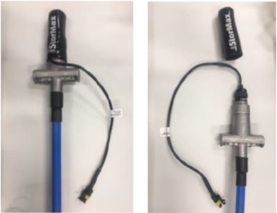
4. Unscrew the cable’s head (counterclockwise)
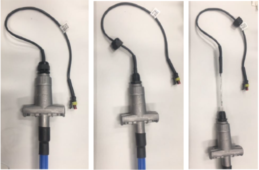
5. Pull the element out of the tubing.
6. Insert the new temperature element (always with the short circuit connector plugged in) into
the tubing, ensuring it goes all the way down so the element’s head fits perfectly into the
receptacle of the tubing, then screw the element’s plastic head to secure it.
7. Ensure interconnect (INT2) cable is good by verifying electrical continuity of each one of the interconnect wires (white and black wires):
i. Unplug wires’ ends from the RTU/Line Expander/Cable Node at RTU/Line
Expander/Cable Node connectors, then joint and twist them. Then,
ii. With an electrical Multitester/Multimeter check for electrical continuity
between Interconnect cable’s wires at the cable’s end: it should generate a
continuous “beep” (if function selector on continuity) or present a very low
electrical resistance (under 10 Ohms -will depend pretty much on the length of
the INT2, if function selector on Resistor), otherwise, it would mean
Interconnect cable issues and would have to be replaced and the new one
tested to make sure it is good.
iii. Once Interconnect cable’s health has been verified, put everything back to
normal → reconnect INT2 cable’s wires to the RTU/Line Expander/Cable Node
connectors
8. Remove the short circuit connector from the Cable/element’s head and connect it to the Interconnect cable’s connector ensuring a good connection.
9. Put the cable’s cap back onto the cable’s head.
10. For Integris systems: Either Cycle the power on the corresponding RTU or send a RTU Reset command through the “Diagnostics” tab from Integris software, so to allow for the cable(s) to get recognized by the RTU.
For OPIBLUE systems: Unmap and remap the corresponding cable node, so to allow for the cable(s) to get recognized by the cable node (CN01/CN08).
P.S. If, for whatever reason a good cable needs to be left unplugged, ensure it is left short circuited either by joining and twisting white and black wires at the RTU/Line Expander end, or by using an electrical short circuit terminal connected to the cable/element’s head. This will prevent cable/element damage by ESD.