![OPI_with_Tag_RGB_300dpi_3in_tall-1.png]](https://knowledge.opisystems.com/hs-fs/hubfs/OPI_with_Tag_RGB_300dpi_3in_tall-1.png?height=50&name=OPI_with_Tag_RGB_300dpi_3in_tall-1.png)
Must Have Tools & Equipment
- Philips screwdriver
- 1/8” flathead screwdriver
- 7/16” wrench
- 1” socket with ratchet
- Cordless Drill with 3/8” Nut Driver
- Drill Step Bit
- Wire stripper
- Cable Node Jumper or a magnet
Removal of Existing Non-CO2 Hardware in MG.com
- In MG.com under System Settings go into Sites and Bins and locate the bin you are going to be adding the Grain Quality Sensor(s) to.
- Select Cables then click the Edit button.
- Remove all cables from the selected bins.
- Under System Settings go to Nodes then navigate to the specific node that is associated with the bin that you have just unmapped cables from.
- Unmap the selected Cable Node from the Gateway.
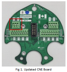
Adding the Headspace (CO2) & New Cable Node (CNE Board
- Open the Cable Node up by loosening the 3 Philips screws with the Philips screwdriver.
- Put the red jumper back on the Cable Node to power it down. Note: If you do not have the red jumper handy you will need a magnet to reset the Cable Node after the new CNE board has been installed and the cables and headspace sensor have been connected. This is necessary so they can be recognized by the new CNE board that has been installed in the Cable Node.
- Disconnect the cables from the terminations.
- Using a Philips screwdriver remove the 3 screws (2 from CNE Board & 1 securing the tether) from the existing Cable Node Expander (CNE Board) from the (old) Cable Node base.
- Take the new updated Cable Node Expander (CNE Board) place in the Cable Node base and secure in place using the 3 screws. (2 for the CNE Board & 1 securing the tether in place)
- Terminate the interconnect wire from each cable into the applicable channel on the Cable Node Expansion Board. (Note: Each cable goes into the same channel as it was from the original Cable Node.)
- Remove the 1” (25 mm) plug from the bottom of the Cable Node base. (A 1” or 25 mm socket with rachet will work best.)
- Feed the INT3 from the Headspace Grain Quality Sensor in through the ½’ opening and connect the INT3 (Red/White/Black) into the 3-wire termination. (Note: Make sure the INT3 from the Headspace Grain Quality Sensor is cut to length prior to in being connected.)
- There is a ½’ Cord Grip on the INT3 connected to the Headspace Grain Quality Sensor this Cord Grip needs to be put into the ½’ opening on the Cable Node base. Using a wrench secure it in place to create a watertight seal around the INT3 cable from the headspace sensor.
- Remove the red jumper to activate the Cable Node.
- Place the clear dome back on the Cable Node base and tighten the 3 Philips screws to secure in place. Note: If you don’t have the red jumper as previously mentioned, you will need to run a magnet down the side of the clear dome along the vertical pcb board to reset the Cable Node. Once reset the LED light will continue to flash until the Cable Node has been remapped to the Gateway.
Adding the Headspace (CO2) & New Cable Node (CN08) into www.managegrain.com
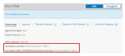
- 1. In www.managegrain.com under System Settings go to Nodes then map the Cable Node back to the Gateway. Once the remapping of the Cable Node is complete, you should see FNR firmware at 8.14 and the Fan Node firmware at 8.22 once it has been remapped to the Gateway.
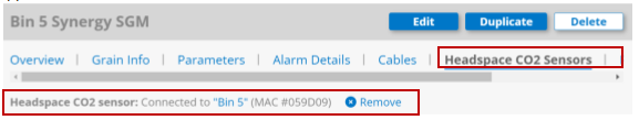
- Under the System Settings go into Sites and Bins and locate the bin you are going to be adding the Grain Quality Sensor(s) to. Once you have added the Headspace CO2 Sensor to the bin it will appear as shown below.
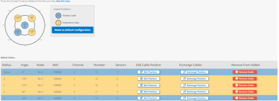
- Remap the cables back into the bin as they had been previously unmapped in the process.
 The Headspace CO2 Sensor has now been added and will provide hourly readings at the same time in which the cable readings for the bin are taken.