![OPI_with_Tag_RGB_300dpi_3in_tall-1.png]](https://knowledge.opisystems.com/hs-fs/hubfs/OPI_with_Tag_RGB_300dpi_3in_tall-1.png?height=50&name=OPI_with_Tag_RGB_300dpi_3in_tall-1.png)
Fan control components
- Fan Node outputs Fan1 and Fan2
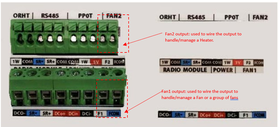
- Fan1 output: used to wire the output to handle/manage a Fan or a group of fans.
- Fan2 output: used to wire the output to handle/manage a Heater.
Fan relay
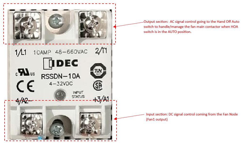
This component has an input section (signal control coming from the Fan Node unit – Fan1 ouptut, usually a DC signal {+5 or +12} VDC) and an output section that is meant to handle the main contactor of a fan (usually a AC output {110 or 220} ACV)
HOA Switch: Hand Off Auto (Man Auto Off) Switch
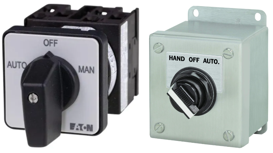
This component is meant to allow for a manual (MAN/HAND) operation of the fan, or an AUTO operation (controlled by the signal control coming form the Fan Relay), or to disable (turn OFF) the fan operation.
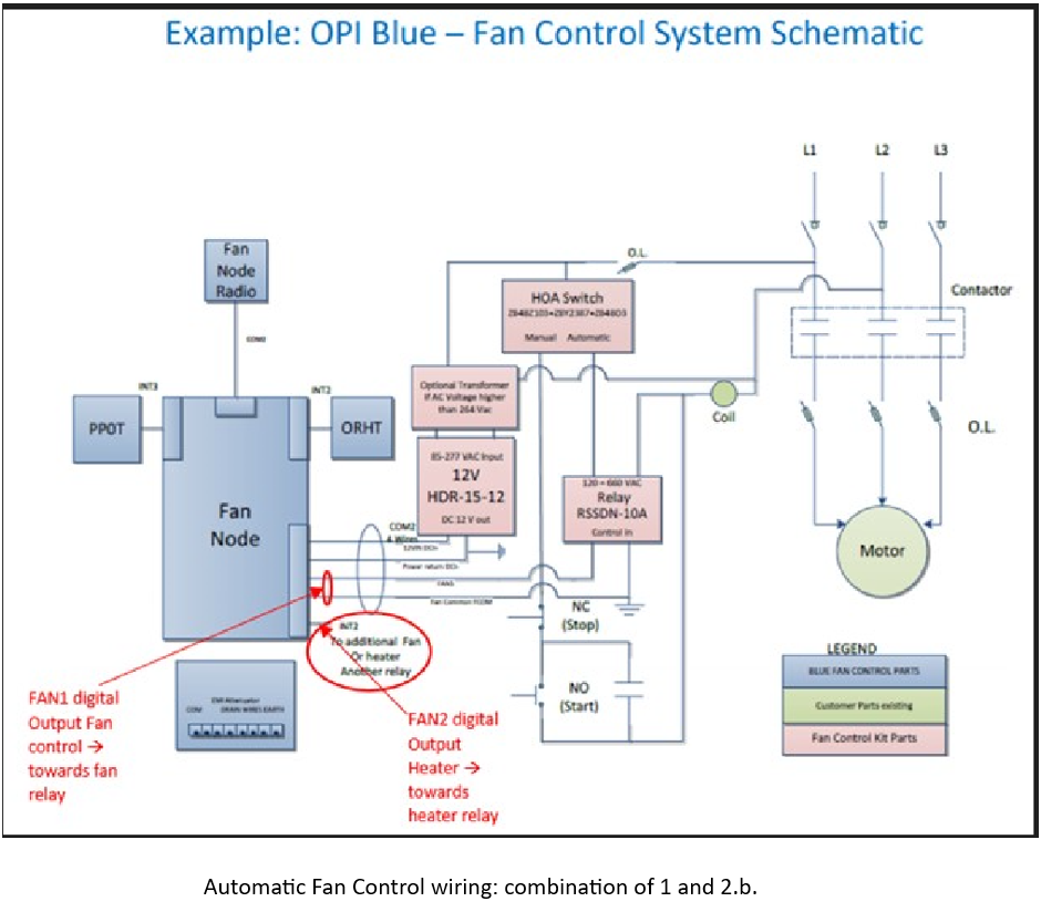
Wiring of the Automatic Fan Control System
- Wire connected to Fan1 output (on Fan Node unit) goes to the Relay +3/A1 input and the FCOM wire from the same Fan1 output connector goes to the 4/A2- input connector of the relay:
- From the relay output section
- 1/L1 terminal goes to the L1 (220 phase) and 2/T1 goes to the AUTO position of the HOA switch, or
- 1/L1 terminal going to the AUTO position of the HOA switch and the 2/T1 terminal going to the main coil that handles the contactors of the fan motor (figure below)
Heater
Heater is handled/managed by the Fan2 output terminal (F2 and FCOM wires) of the Fan Node terminal.